
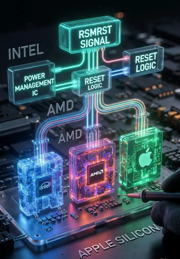
RSMRST# signal working principle is one of the most searched topics in chip-level repair, because this single signal decides whether your board boots or stays dead. Without RSMRST# going HIGH, no CPU initializes, no clock starts, no POST begins. Every dead board on your bench starts with checking this signal first.
Before reading this, if you have not read our Power Well guide, start there first: Power Well: The Foundation of Laptop
Motherboard Chip Level Repair
Table of Contents
What is RSMRST# Signal ?
RSMRST# stands for Resume Well Reset. The # symbol means it is an Active-Low signal — the signal is active (doing its job) when voltage is LOW (0V). When the system is running normally, this signal must be HIGH (3.3V).
Simple way to remember it: RSMRST# Signal is the “permission signal” for the main controller chip. Until this signal goes HIGH, nothing on the board initializes — no CPU, no clock, no POST.
| Signal State | Voltage | Meaning |
|---|---|---|
| LOW (Active) | 0V | System held in RESET — nothing starts |
| HIGH (Released) | 3.3V | System has permission to boot |
RSMRST# vs RTCRST# — Important Difference
These two signals confuse many technicians. Here is the clear difference:
| Signal | Full Name | What It Resets | When Used |
|---|---|---|---|
| RSMRST# | Resume Well Reset | PCH / Main controller — RTC domain stays alive | Every normal boot |
| RTCRST# | RTC Reset | Everything including RTC domain — deepest reset | Only in extreme cases |
Key point: RTCRST# is deeper than RSMRST#. In most dead board cases, you are dealing with RSMRST# — not RTCRST#.
RSMRST# and ACPI Power States
Understanding how RSMRST# behaves across different power states helps you know what to expect during testing:
| Power State | Description | RSMRST# State |
|---|---|---|
| S0 | System fully ON | HIGH |
| S0ix | Modern Standby (low power idle) | HIGH |
| S3 | Suspend to RAM | HIGH — system suspended, not reset |
| S4 | Hibernate | LOW — full reset needed on resume |
| S5 | Soft OFF | LOW — system appears off |
Important: In S3 (Sleep), RSMRST# stays HIGH because the system is suspended — not reset. Do not confuse a sleeping board with a dead board.
RSMRST# Signal on Intel Platform
On Intel motherboards, RSMRST# resets the PCH (Platform Controller Hub) — the chip that controls USB, SATA, audio, and the entire boot process.
Intel Boot Flow
Power ON
  → PMIC/EC generates VSBS (3.3V Standby rail)
  → EC verifies all standby rails are stable
  → EC releases RSMRST# → goes HIGH to PCH
  → PCH initializes
  → PCH sends PLTRST# HIGH to CPU
  → CPU starts executing BIOS
  → POST begins → Display output
How Intel Architecture Evolved (Gen 1 to Gen 16)
RSMRST# core function has remained the same across all Intel generations, but the platform architecture around it has changed significantly:
| Generation | Platform | Architecture Change |
|---|---|---|
| Gen 1–4 | Nehalem → Haswell (2008–2014) | PCH was a separate chip. RSMRST# directly controlled PCH. External pull-down resistors commonly used. |
| Gen 5–10 | Broadwell → Comet Lake (2014–2020) | PCH integration increased. EC firmware role became critical. RSMRST# timing tightly linked to multiple power domains (Vccio, Vccst, Vccprim). |
| Gen 11–13 | Tiger Lake → Raptor Lake (2020–2023) | CPU and PCH moved on-package (SoC approach). Multiple power domains — primary, secondary, GT, SA. RSMRST# coordinates all of them. |
| Gen 14–16 | Meteor Lake → Arrow Lake (2023–2024) | Tile-based architecture. SoC-LP chipset design. RSMRST# coordinates multiple dies/tiles power-up. Deep S5 and Modern Standby tightly integrated. |
Bottom line for technicians: On modern Intel platforms (Gen 11+), RSMRST# failure makes the board appear completely dead — even more so than older platforms — because the CPU and PCH are in the same package.
RSMRST# Signal on AMD Platform
AMD documentation does not always use the term “RSMRST#” directly, but the reset logic concept is identical. The equivalent chip on AMD is the FCH (Fusion Controller Hub).
AMD Equivalent Signal Names
| AMD Signal Name | Intel Equivalent | Function |
|---|---|---|
| RSMRST_L | RSMRST# | Primary system reset — releases FCH |
| SYS_RESET# | RSMRST# | Platform reset signal |
| SYS_PWROK / PWR_OK | PWROK | Power good indication |
| RTC_RESET# | RTCRST# | RTC domain reset |
AMD Boot Flow
Power ON
  → Power rails stable
  → SYS_PWROK / PWR_OK asserts
  → RSMRST_L / SYS_RESET# de-asserts (goes HIGH)
  → FCH initializes
  → AMD PSP (Platform Security Processor) starts
  → CPU cores receive power and clock
  → BIOS/UEFI executes → POST
Important AMD-specific note: The PSP (Platform Security Processor) must complete its initialization before the main CPU cores start. On AMD platforms, RSMRST# equivalent being HIGH does not guarantee boot — if PSP has an issue, the board will still be dead. Always check PSP-related power domains on Ryzen platforms before concluding the reset chain is the problem.
On modern AMD Ryzen 4000–7000 series, the CPU and FCH are integrated into a single SoC — similar to Intel’s approach. The EC still generates the initial reset release signal, but the signal path is internal to the SoC on newer designs. Always refer to the specific boardview and schematic for exact signal names.
RSMRST# Signal on Apple Silicon (M1 / M2 / M3)
Apple Silicon Macs do not use Intel PCH or AMD FCH. Everything — CPU, GPU, Neural Engine, memory controller — is integrated into one SoC. So RSMRST# as a separate external signal does not exist in the traditional sense.
However, the concept is identical. On Apple Silicon MacBooks, this function is handled by the PMU (Power Management Unit) inside the SoC, coordinated through the USB-C power delivery system.
Apple Silicon Boot Flow
USB-C charger connected
  → CD3217 (USB-C Power Delivery chip) negotiates power
  → VBUS established
  → PPBUS_G3H (main battery bus) forms — 3.3V–4.35V
  → PP3V3_G3H standby rail becomes available
  → PMU releases internal SoC reset (equivalent to RSMRST# HIGH)
  → iBoot (Apple bootloader) executes
  → macOS boots
Key Signals on Apple Silicon
| Apple Signal | Equivalent Role | Notes |
|---|---|---|
| PPBUS_G3H | Main standby power (like VSBS) | Must be present for PMU to work |
| PP3V3_G3H | 3.3V standby rail | Powers PMU logic |
| CD3217 | USB-C PD controller | Failure here = PMU never releases reset |
| PMU reset release | RSMRST# equivalent | Internal to SoC — not a separate test point |
If PPBUS_G3H is missing or CD3217 is faulty, the PMU never releases its internal reset — the board appears completely dead, exactly like RSMRST# stuck LOW on Intel/AMD.
Quick Reference — Platform Comparison
| Platform | Reset Controller | Signal Name | Generated By | Goes To |
|---|---|---|---|---|
| Intel | PCH | RSMRST# | EC | PCH → PLTRST# → CPU |
| AMD | FCH / SoC | RSMRST_L / SYS_RESET# | EC | FCH → PSP → CPU cores |
| Apple Silicon | PMU (inside SoC) | Internal (no external pin) | CD3217 + PPBUS | SoC internal → iBoot |
Key Takeaways
- RSMRST# is Active-Low — 0V means reset active, 3.3V means system can run
- It is the first gate in the boot chain — without it, nothing initializes
- On Intel: EC generates RSMRST# → PCH → PLTRST# → CPU
- On AMD: Same concept, different signal names — also check PSP after reset releases
- On Apple Silicon: PPBUS_G3H + CD3217 perform the equivalent function internally
- In S3 sleep, RSMRST# stays HIGH — do not confuse a sleeping board with a dead one
- On modern platforms (Gen 11+ Intel, Ryzen 4000+ AMD, M1+), reset failure = completely dead board because CPU and controller are in the same package
Understanding RSMRST# Signal gives you a logical starting point for every dead board case. The signal name may change across platforms, but the working principle is always the same — it is the system’s permission to start.
Also available in Hinglish: If you prefer reading this topic in Hinglish, our detailed guide is available on EzoneCare — RSMRST#
(Resume Reset) Signal Working Principle (Hinglish) https://ezonecare.com/rsmrst-resume-reset-signal/
We have done our best to cover this topic as completely as possible. However, chip-Level repair is a deep field and there
is always more to learn. If you feel we have missed something, made an error, or if you have a real bench experience related to this topic, please share it with us. Drop a comment below or write to us at support@werefix.in. We will review and update the article. Good knowledge, shared freely, makes every technician better.
This article was last reviewed: March 2026
This article is part of the RSM_RST# Master Trainer Series – Chip Level Repair Education | WeRefix.in Team
.