
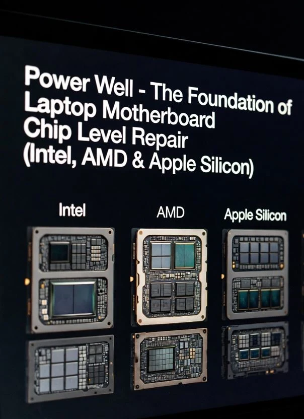
Power well chip level repair is the starting point for every laptop technician — because before any signal fires, before RTCRST# releases, before RSMRST# activates, before the CPU receives a single volt, the Power Wells must be alive and stable. Every dead board you have ever seen on your bench had one thing in common: at least one Power Well had failed. If you have been replacing components without first checking the Power Wells, you have been guessing, not repairing.
This guide is part of our Chip Level Repair Signal Series. If you want to understand how RTCRST# and RSMRST# fit into the bigger picture, this is the foundation you need to read first.
Table of Contents
What is a Power Well?
A Power Well is a dedicated power domain on the motherboard — a section of the chipset that has its own independent power supply, its own ON/OFF control, and its own group of circuits that it powers.
Think of it this way. Your house has a main electricity connection — but inside, different rooms have different switches. You can turn off the bedroom without turning off the kitchen. Power Wells work exactly the same way inside a laptop chipset.
Each Power Well:
- Has its own voltage rail
- Powers a specific group of circuits
- Can be turned ON or OFF independently
- Has a defined sequence — some must come ON before others
This is not just an academic concept. When a board is dead, one of the first questions is — which Power Well is missing? That single answer tells you exactly where to look.
Why Does a Laptop Have Multiple Power Wells?
A laptop is not always fully ON or fully OFF. It moves through different states — running, sleeping, hibernating, soft off. In each state, different parts of the board need power and others do not.
If every circuit on the board was always powered, the battery would drain even when the laptop is completely off. That is not acceptable. So the chipset is divided into Power Wells — each one comes alive only when needed.
| System State | ACPI State | What is Powered |
|---|---|---|
| Laptop fully ON | S0 | All Power Wells active |
| Display off, RAM active | S3 — Sleep | Suspend Well + RTC Well only |
| Hibernating | S4 | RTC Well only |
| Soft OFF — plugged in | S5 | RTC Well only |
| Battery removed | G3 — Mechanical OFF | Nothing — completely dead |
This is the direct connection between Power Wells and ACPI states — and this is exactly why understanding Power Wells makes every other signal on the board easier to understand.
The Three Core Power Wells on Intel Platforms
On Intel platforms (which most laptops use), the PCH (Platform Controller Hub) is divided into three main Power Wells. Each one has a name, a voltage, and a job.
1. RTC Well — Always On
The RTC Well is the deepest, most fundamental Power Well on any Intel motherboard. It is powered by VRTC — typically 3.3V — which comes from the CMOS coin cell battery or the system standby power, whichever is available.
The RTC Well powers:
- The Real Time Clock — date and time
- CMOS memory — BIOS settings
- The 32.768 kHz crystal oscillator circuit
- RTCRST# and SRTCRST# reset logic
This Well never turns off as long as any power source exists. Even in G3 mechanical off state, if the coin cell battery is present, the RTC Well stays alive. This is why your laptop remembers the time even after being switched off for weeks.
When the RTC Well dies — BIOS settings reset, clock loses time, and the board may completely refuse to boot. We covered this in detail in our RTCRST# Signal guide.
2. DSW Well — Deep Sleep Well (Intel Gen 6 to Gen 10)
The DSW Well (Deep Sleep Well) is a platform-specific power domain found on Intel Gen 6 (Skylake) through Gen 10 (Comet Lake) platforms. It sits between the RTC Well and the Suspend Well in the power sequence — acting as a bridge that keeps certain circuits alive during deep sleep (S4/S5) states without activating the full Suspend Well.
The DSW Well runs on VCCDSW3_3 (3.3V) and is responsible for:
- Ultra-low power standby management in S4/S5
- Wake event detection during deep sleep
- Battery presence detection logic
- Fast resume support from hibernation
From Intel Gen 11 (Tiger Lake) onwards, the DSW Well was merged into the Suspend Well — so on modern platforms you will not find a separate VCCDSW rail. On AMD platforms, a similar concept exists under different rail names. For repair: on Gen 6 to Gen 10 Intel boards, if the RTC Well is healthy but the board is still completely dead, always check VCCDSW3_3 before suspecting the PCH.
3. Suspend Well — Active from S3 to S0
The Suspend Well comes alive as soon as the adapter or battery is connected — even before the power button is pressed. It runs on VCCSUS3_3 (3.3V Suspend) and VCCSUS1_8 (1.8V Suspend) rails.
The Suspend Well powers:
- The EC — Embedded Controller
- USB power delivery circuits
- Power button detection logic
- Wake-on-LAN and wake-on-USB circuits
- RSMRST# reset logic
This is the Well that listens for the power button press. Without the Suspend Well, pressing the power button does nothing — the board cannot even detect that you pressed it.
The RSMRST# signal — which we covered in our RSMRST# Signal guide — belongs to this Well. When the Suspend Well is healthy and stable, RSMRST# releases and the boot sequence begins.
3. Core Well — Active Only in S0
The Core Well is the main operating domain. It only comes alive after the power button is pressed and the Suspend Well gives the go-ahead. It runs on multiple rails — VCC3_3, VCC5, VCC1_8 and others depending on the platform.
The Core Well powers:
- CPU and RAM initialization circuits
- PCIe lanes — GPU, NVMe, WiFi
- Display output circuits
- Audio, USB 3.0, and other high-speed interfaces
- PLTRST# reset logic
When the Core Well fails to come up — the board powers on (fan may spin), but there is no POST, no display, no beep. This is the most common “dead board” scenario in chip level repair.
How the Three Wells Power Up — The Sequence
The sequence is strict. Each Well must be stable before the next one starts. This is called the Power Sequencing and it is controlled by the EC working with the PCH.
Adapter or Battery Connected
        ↓
RTC Well activates (VRTC stable)
        ↓
RTCRST# releases — RTC domain alive
        ↓
DSW Well activates (VCCDSW3_3 stable) — Intel Gen 6–10 only
        ↓
Suspend Well activates (VCCSUS3_3 stable)
        ↓
EC powers up — starts monitoring
        ↓
RSMRST# releases — PCH initializes
        ↓
Power button pressed
        ↓
Core Well activates (VCC3_3, VCC5 stable)
        ↓
PLTRST# releases — CPU starts
        ↓
BIOS POST begins
Key point for repair: If any Well fails to come up, the sequence stops at that point. The board does not skip a step — it simply stops. Knowing this sequence tells you exactly which Well to check based on what symptom you see.
Power Wells on AMD Platforms
AMD platforms use the same concept but with different naming. On AMD, the chipset is called the FCH — Fusion Controller Hub, and on modern Ryzen designs the FCH is integrated inside the SoC itself.
| Intel Well | AMD Equivalent | Function |
|---|---|---|
| RTC Well (VRTC) | RTC Domain (VRTC) | Always-on, coin cell powered |
| Suspend Well (VCCSUS) | Standby Domain (VSB) | EC and wake circuits |
| Core Well (VCC) | Main Domain (VDDIO/VDD) | CPU, RAM, full system |
On Ryzen 4000 and newer, the power management is handled more aggressively inside the SoC — the PSP (Platform Security Processor) controls power gating for individual cores and subsystems. But from a repair perspective, the three-domain concept still applies — RTC domain, Standby domain, and Main domain.
Power Wells on Apple Silicon (M1 / M2 / M3)
Apple Silicon takes Power Well management to a completely different level. The entire SoC CPU, GPU, Neural Engine, and memory controller is divided into multiple fine-grained power domains managed entirely by the PMU (Power Management Unit) inside the chip.
From a repair perspective, the key power domains on Apple Silicon MacBooks are:
- PPVCC_S0 domain — Main SoC power, active only in S0
- PPVCC_S3 domain — Sleep state power
- PPVCC_S5 domain — Soft off, always-on management
- PPBUS_G3H — The deepest always-on rail, equivalent to the RTC Well
If PPBUS_G3H is missing on an Apple Silicon board, the PMU cannot initialize — the board is completely dead with no response whatsoever. This is the Apple equivalent of a dead RTC Well on Intel.
Power Well Failures — What You See on the Bench
Understanding which Well has failed tells you exactly what symptom to expect — and more importantly, where to measure.
| Failed Well | Symptom | What to Check |
|---|---|---|
| RTC Well | BIOS resets, clock loses time, may not boot | VRTC voltage, coin cell, 32.768kHz crystal |
| Suspend Well | Power button does nothing, board completely dead | VCCSUS3_3 rail, EC power, RSMRST# signal |
| Core Well | Fan spins, no display, no POST | VCC3_3, VCC5 rails, PLTRST# signal |
This table is your first diagnostic step on any dead board. Before touching anything, identify which Well is missing. Everything else follows from there.
Quick Reference — Power Well Summary
| Well | Voltage Rails | Active In | Key Signal |
|---|---|---|---|
| RTC Well | VRTC 3.3V | Always — even G3 | RTCRST# |
| DSW Well | VCCDSW3_3 | S5, S4 — Intel Gen 6–10 only | DSW_PWRGD |
| Suspend Well | VCCSUS3_3, VCCSUS1_8 | S5, S4, S3, S0 | RSMRST# |
| Core Well | VCC3_3, VCC5, VCC1_8 | S0 only | PLTRST# |
The EC — Embedded Controller and Power Wells
The EC (Embedded Controller) is the unsung hero of laptop power management. It lives inside the Suspend Well — powered by VCCSUS — and is the first intelligent circuit to wake up when you connect the adapter or battery.
The EC acts as the manager between the user and the Power Wells:
- Power button press — EC receives it first, decides whether to allow boot
- Battery communication — EC talks to the battery via SMBus, reports charge level
- Charging control — EC enables or disables the charging circuit
- Thermal management — EC monitors temperature and controls fan speed in real time
From a repair perspective, if the Suspend Well is present but the power button still does nothing, the EC is the first suspect. A corrupted EC firmware or a dead EC clock can make the board behave exactly like a dead Suspend Well. Always verify EC voltage and EC clock oscillation before concluding the PCH is faulty. On most platforms, EC can be reprogrammed using a CH341A or dedicated EC programmer — this alone fixes a significant number of “dead board” cases where all power rails are present, but nothing responds.
Key Takeaways
- A Power Well is an independent power domain — each one powers a specific group of circuits
- There are three core Wells on Intel platforms — RTC Well, Suspend Well, and Core Well
- RTC Well is always on — as long as any power source exists
- Suspend Well activates when adapter or battery connects — before power button press
- Core Well activates only after power button — this is where POST begins
- Each Well has a key reset signal — RTCRST#, RSMRST#, PLTRST# respectively
- Power sequencing is strict — one Well must be stable before the next starts
- On AMD — same concept, different names. On Apple Silicon — PMU manages everything internally
- Dead board diagnosis starts here — identify the failing Well first, everything else follows
Now that you understand Power Wells, every other signal on the board has context. RTCRST# belongs to the RTC Well. RSMRST# belongs to the Suspend Well. PLTRST# belongs to the Core Well. The reset chain is simply the Power Wells coming alive one by one — in sequence, in order, every single time the board powers on.
If you prefer reading this topic in Hinglish, our detailed guide is available on EzoneCare.
https://ezonecare.com/laptop-motherboard-power-wells-complete-chip-level-repair-guide/
Please Note
We have done our best to cover this topic as completely as possible. However, chip-level repair is a deep field — and there is always more to learn.
If you feel we have missed something, made an error, or if you have a real bench experience related to this topic- please share it with us. Drop a comment below or write to us at support@werefix.in – we will review and update the article.
Good knowledge, shared freely, makes every technician better.
This article was last reviewed: March 2026
Next in this series: PLTRST# Signal — Platform Reset Working Principle
This article is part of the Chip Level Repair Signal Series — Chip Level Repair Education | WeRefix.in Team