
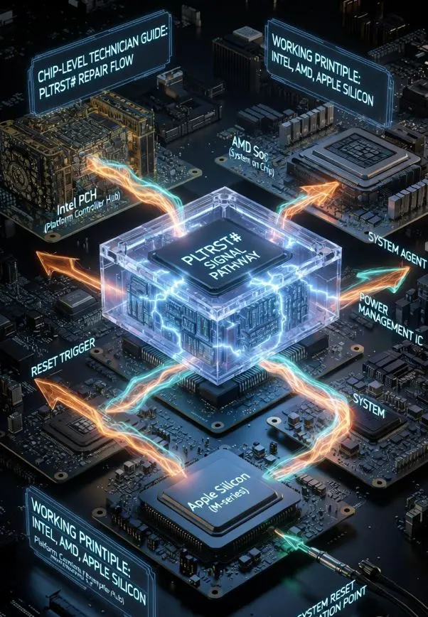
PLTRST# signal chip level repair is where the boot chain finally reaches the CPU — because PLTRST# is the last reset signal in the sequence, and when it releases, the processor executes its very first instruction. Every signal before this — RTCRST#, RSMRST# — was preparation. PLTRST# is the moment the platform actually begins execution.
This guide is part of our Chip Level Repair Signal Series. If you have not read the earlier guides, we recommend starting with our Power Well guide first it explains the foundation that makes PLTRST# possible. You may also want to read our RTCRST# guide and RSMRST# guide before this one — the three signals work as a chain.
Table of Contents
What is PLTRST#?
PLTRST# stands for Platform Reset. Like all reset signals, the # means it is Active-Low — when the signal is LOW (0V), the entire platform is held in reset. When it goes HIGH (3.3V), the platform is released and the CPU begins executing code.
PLTRST# is generated by the PCH (Platform Controller Hub) on Intel platforms and sent simultaneously to multiple components across the board — the CPU, RAM controller, PCIe devices, USB controllers, audio chip, and more. It is a broadcast reset — one signal that releases the entire platform at the same moment.
| Signal | Generated By | Resets | When It Happens |
|---|---|---|---|
| RTCRST# | Power loss detection | RTC domain only | Only on VRTC loss |
| RSMRST# | EC firmware | PCH / FCH | Every power cycle |
| PLTRST# | PCH / FCH | Entire platform — CPU, RAM, PCIe | Every boot — after power button |
Where Does PLTRST# Fit in the Boot Chain?
To understand PLTRST#, you need to see exactly where it sits in the complete power and reset sequence. Every step below must be completed successfully before PLTRST# can release:
Adapter or Battery Connected
        ↓
RTC Well activates → RTCRST# releases
        ↓
Suspend Well activates → EC powers up
        ↓
RSMRST# releases → PCH initializes
        ↓
Power button pressed
        ↓
Core Well activates (VCC3_3, VCC5 stable)
        ↓
PCH verifies all power rails are stable
        ↓
PCH verifies PWROK signal is HIGH
        ↓
PLTRST# releases (goes HIGH) ← YOU ARE HERE
        ↓
CPU exits reset and receives the first clock cycle
        ↓
CPU fetches first instruction from BIOS ROM
        ↓
BIOS POST begins
Key point for repair: PLTRST# cannot release until the Core Well is fully stable. If any core power rail is missing or unstable, the PCH will hold PLTRST# LOW indefinitely — the board appears powered on but completely dead.
What Does PLTRST# Actually Reset?
PLTRST# is a broadcast signal — it goes to multiple destinations simultaneously. Understanding exactly what it resets tells you what fails when it does not release properly:
CPU Reset
The CPU receives PLTRST# and uses it as its primary reset input. When PLTRST# is LOW, the CPU is completely inactive — no instruction fetch, no cache activity, no power consumption beyond standby. The moment PLTRST# goes HIGH, the CPU’s internal reset logic initializes all registers to their default state and begins fetching the first instruction from the reset vector address — which points to the BIOS ROM.
Memory Controller Reset
On modern Intel platforms (Gen 5+), the memory controller is inside the CPU itself. PLTRST# resets the memory controller simultaneously with the CPU — ensuring RAM training starts from a clean state every boot. If PLTRST# is unstable or bouncing, RAM training will fail and the board will show no POST.
PCIe Reset
PLTRST# is routed to all PCIe devices on the board — discrete GPU, NVMe SSD, WiFi card, and PCIe-connected chips. All these devices wait for PLTRST# to release before initializing. This is why a board can appear to power on (fans spin, LEDs light) but have no display — the GPU is still held in reset because PLTRST# never released properly.
USB and Other Controllers
USB 3.0 controllers, SATA controller, audio chip, and other PCH-managed interfaces all receive PLTRST# simultaneously. After release, each device goes through its own internal initialization sequence before becoming functional.
PLTRST# on Intel Platform
How Intel Generates PLTRST#
On Intel platforms, PLTRST# is generated entirely by the PCH. The PCH will only release PLTRST# when all of the following conditions are met:
- RSMRST# is HIGH — PCH itself has been properly initialized
- PWROK is HIGH — All core power rails are stable and within spec
- VCCST_PWRGD is HIGH — Suspend well power good signal asserted
- SUS_STAT# is LOW — Suspend state is not active
- Core Well voltage stable — VCC3_3, VCC5 within tolerance
If any one of these conditions is not met, the PCH holds PLTRST# LOW. This is the PCH’s way of saying — “the platform is not ready, CPU must wait.”
Intel Generation-wise PLTRST# Evolution
| Generation | Platform | PLTRST# Behavior |
|---|---|---|
| Gen 1–4 | Nehalem → Haswell (2008–2014) | PLTRST# goes directly to CPU socket pin. Separate PCH chip — easy to trace on schematic. External pull-up resistor commonly visible. |
| Gen 5–10 | Broadwell → Comet Lake (2014–2020) | PCH integration increased. PLTRST# still external but EC firmware coordination became tighter. PWROK sequencing became more critical. |
| Gen 11–13 | Tiger Lake → Raptor Lake (2020–2023) | CPU and PCH on same SoC package. PLTRST# generation is internal to the SoC, but the reset may still be routed externally to platform devices depending on board design — no dedicated external test point in many cases. PCH tile generates it internally. |
| Gen 14–16 | Meteor Lake → Arrow Lake (2023–2024) | Tile-based architecture. PLTRST# coordinates reset across multiple compute tiles. Recovery time after PLTRST# is longer due to multi-tile synchronization. |
PWROK — The Gate Before PLTRST#
PWROK (Power OK) is a critical signal that must be understood alongside PLTRST#. PWROK is generated by the power management circuit and tells the PCH that all core power rails are stable. The PCH will not release PLTRST# until PWROK is HIGH.
Core Well rails stable (VCC3_3, VCC5)
        ↓ (100ms typical delay)
PWROK goes HIGH
        ↓ (10ms typical delay)
PCH releases PLTRST# HIGH
        ↓
CPU starts
Important for repair: If PWROK is missing or delayed, PLTRST# will never release — even if all power rails look correct on a multimeter. Always verify PWROK signal with an oscilloscope when diagnosing no-POST situations on Intel platforms.
Typical PLTRST# Timing
For bench diagnosis, knowing the expected timing helps identify whether a delay is normal or a fault:
Power button pressed
        ↓
Core Well rails stabilize
        ↓ (0 – 100ms typical)
PWROK asserts HIGH
        ↓ (5 – 20ms typical)
PCH releases PLTRST# HIGH
        ↓
CPU exits reset → first instruction fetch begins
What this means on the bench: If PLTRST# takes more than 200ms after power button press — or never goes HIGH — the fault is in PWROK generation or the core power rails feeding it. Use an oscilloscope to capture the exact timing. A multimeter will show voltage but cannot show timing delays.
PLTRST# on AMD Platform
On AMD platforms, the equivalent signal is called SYS_RESET# or PLTRST_L depending on the specific platform. The function is identical — it is the final platform-wide reset that releases the CPU and all connected devices.
AMD Reset Flow
| AMD Signal | Intel Equivalent | Function |
|---|---|---|
| SYS_RESET# | PLTRST# | Platform-wide reset — CPU, PCIe, USB |
| PLTRST_L | PLTRST# | Same signal, different naming on some platforms |
| PWR_GOOD | PWROK | All rails stable — gate before reset release |
On AMD Ryzen platforms, there is an important additional step — the PSP (Platform Security Processor) must complete its initialization before SYS_RESET# releases to the CPU cores. The PSP runs AMD’s secure boot firmware and validates the system before allowing the main CPU cores to start. This is why AMD platforms sometimes take slightly longer from power button press to first BIOS screen compared to equivalent Intel platforms.
AMD Boot Flow with PLTRST# Equivalent
Power button pressed
        ↓
Core power rails stable
        ↓
PWR_GOOD asserts HIGH
        ↓
FCH initializes
        ↓
PSP starts — validates secure boot chain
        ↓
PSP releases SYS_RESET# HIGH
        ↓
CPU cores initialize
        ↓
AGESA firmware executes (AMD BIOS init)
        ↓
POST begins
PLTRST# on Apple Silicon (M1 / M2 / M3)
Apple Silicon does not have a PLTRST# signal in the traditional sense. The entire SoC — CPU cores, GPU, Neural Engine, memory controller, and I/O — is reset and initialized internally by the PMU (Power Management Unit) inside the chip.
However, the concept exists. On Apple Silicon MacBooks:
- The PMU manages internal reset sequencing for all compute tiles within the SoC
- PPBUS_G3H must be present and stable before the PMU can begin its internal reset sequence — this is the Apple equivalent of PWROK
- The CD3217 USB-C PD controller coordinates power delivery and signals the PMU when power is stable enough to begin initialization
- Once the PMU releases its internal reset, the iBoot bootloader begins executing from the secure enclave — equivalent to the CPU fetching its first BIOS instruction on Intel/AMD
Important for Apple repair: If PPBUS_G3H is present but the board remains dead, the PMU’s internal reset sequencing has failed. This is not fixable without either replacing the SoC or addressing the specific power domain failure feeding into the PMU. Unlike Intel/AMD, there is no external PLTRST# test point to verify.
Common Causes of PLTRST# Failure
When PLTRST# does not release on the bench, the cause almost always falls into one of these categories. Check them in this order — from most common to least common:
- Missing or unstable PWROK signal — most common cause. PWROK is generated by the power management circuit. If VCC3_3 or VCC5 core rails are unstable, PWROK will not assert and PLTRST# will stay LOW permanently.
- Core power rail missing or out of tolerance — even if voltage is present, a rail that is slightly low (e.g. VCC3_3 at 2.9V instead of 3.3V) can prevent PWROK from asserting.
- PCH / FCH failure — if the PCH itself is damaged, it may receive PWROK but fail to generate PLTRST#. Rare but possible after liquid damage or ESD events.
- Short on PCIe reset line — PLTRST# is distributed to PCIe devices. A shorted PCIe device (GPU, WiFi, NVMe) can pull the PLTRST# line LOW and prevent release. Remove PCIe devices one by one to isolate.
- BIOS firmware corruption — PLTRST# may release correctly but CPU fetches corrupt code from BIOS ROM, causing immediate shutdown. Board appears to try and fail rather than staying dead.
- Faulty EC firmware — if EC does not complete its power sequencing correctly, RSMRST# may not have released properly, which prevents the PCH from ever generating PLTRST#.
PLTRST# Failures — What You See on the Bench
PLTRST# failures produce very specific symptoms. Knowing these helps you identify the problem before you even touch a multimeter:
| Symptom | What It Means | Where to Check |
|---|---|---|
| Fan spins, LEDs ON, no display | CPU may not be executing code — PLTRST# stuck LOW, or PLTRST# released but BIOS, RAM or GPU rail failed after | PLTRST# signal first, then PWROK, Core Well rails, BIOS chip, RAM |
| Board powers on, shuts off after 3–5 seconds | PLTRST# released but Core Well collapsed — PCH pulled it LOW again | VRM stability, core rail under load |
| No POST, no beep, no display — but charging works | RSMRST# released but PLTRST# stuck LOW | PWROK, core power rails, PCH outputs |
| Random restarts during use | PLTRST# being triggered intermittently | Core Well stability, VRM thermal issues |
| Board dead after BIOS update | BIOS ROM corrupt — CPU fetches garbage after PLTRST# releases | BIOS chip — reprogram with known good file |
How to Check PLTRST# on the Bench
Step 1 — Verify Prerequisites First
Before checking PLTRST# itself, verify that its prerequisites are met. PLTRST# will never release if these are missing:
- RSMRST# must be HIGH — check with multimeter ✅
- Core Well rails must be present — VCC3_3 and VCC5 stable ✅
- PWROK must be HIGH after power button press ✅
Step 2 — Locate PLTRST# Test Point
On Intel Gen 1–10 platforms, PLTRST# is usually accessible:
- Search schematic for “PLTRST”, “PLT_RST”, “SYS_RESET”
- Common locations: near PCH chip, near CPU socket, on PCIe connector pins
- On AMD boards: search for “SYS_RESET#”, “PLTRST_L”
WiFi Slot as a Quick Access Point
On many Intel platforms, the M.2 WiFi slot or Mini PCIe WiFi slot carries PLTRST# on its reset pin — making it a convenient test point without needing to probe directly on the PCH.
- M.2 WiFi slot (Key E): Pin 22 is commonly routed to PLTRST# on many older Intel platforms
- Mini PCIe WiFi slot: Pin 22 is the PERST# / platform reset pin on compatible boards
⚠️ Important: Before probing the WiFi slot, always confirm on the schematic first. On some board designs, this pin may not be connected to PLTRST# at all — it depends entirely on how the board manufacturer has routed the trace. Physically inspect the board as well — if the pad looks isolated or has no visible trace, do not assume the signal is present there.
The WiFi slot tip is a starting point for investigation — not a guaranteed test point. Schematic confirmation is always the correct method.
Step 3 — Measure with Multimeter
Board in S5 state (plugged in, not started):
Expected: PLTRST# = 0V (LOW — held in reset) ✅

Press power button, board starts:
Expected: PLTRST# jumps to 3.3V (HIGH) ✅

If stuck at 0V after power button:
→ Core Well problem or PCH issue
→ Check PWROK signal next
Step 4 — Oscilloscope Verification
For intermittent issues, oscilloscope is essential:
- Probe on PLTRST# pin
- Trigger on rising edge
- Expected: Clean transition from 0V to 3.3V, no bouncing
- Rise time: typically 1–5ms
- If bouncing: unstable core power rail — check VRM
PLTRST# vs RSMRST# — The Critical Difference
These two signals are the most commonly confused in chip level repair. Understanding the difference saves hours of diagnosis time:
| Feature | RSMRST# | PLTRST# |
|---|---|---|
| Generated by | EC firmware | PCH / FCH |
| Goes to | PCH / FCH only | CPU + all platform devices |
| When it releases | When Suspend Well is stable | When Core Well + PWROK stable |
| Power state | Active in S5 — before power button | Active only after power button press |
| If stuck LOW | PCH never initializes — board completely dead | CPU never starts — fan may spin, no POST |
| Voltage | 3.3V HIGH normal | 3.3V HIGH normal |
Simple rule: RSMRST# wakes up the PCH. PLTRST# wakes up everything else. Both must be HIGH for the board to boot — but they happen at different times and for different reasons.
Quick Reference — PLTRST# Summary
| Platform | Signal Name | Generated By | Gate Signal |
|---|---|---|---|
| Intel | PLTRST# | PCH | PWROK must be HIGH |
| AMD | SYS_RESET# / PLTRST_L | FCH / PSP | PWR_GOOD must be HIGH |
| Apple Silicon | Internal PMU reset | PMU inside SoC | PPBUS_G3H must be stable |
Key Takeaways
- PLTRST# is the final reset in the boot chain — when it releases, the CPU executes its first instruction
- PLTRST# is generated by the PCH on Intel and FCH/PSP on AMD — not by the EC
- PWROK must be HIGH before PLTRST# can release — always check PWROK when PLTRST# is stuck LOW
- PLTRST# goes to CPU, RAM controller, PCIe, USB, and all platform devices simultaneously
- On Gen 11+ Intel: PLTRST# is internal to the SoC — no external test point in many cases
- On AMD Ryzen: PSP must complete initialization before SYS_RESET# releases — slightly longer boot time is normal
- On Apple Silicon: No external PLTRST# — PMU manages all resets internally
- Fan spinning with no display = CPU may not be executing code — check PLTRST#, BIOS, RAM and CPU power rails before assuming the cause
- No response after power button = PLTRST# may not have released — check Core Well and PWROK first
With PLTRST# understood, you now have the complete reset chain — RTCRST# resets the RTC domain, RSMRST# wakes the PCH, and PLTRST# releases the entire platform. Every dead board you will ever see falls somewhere in this chain.
Find where the chain breaks, and you find the fault.
Next in this series: Complete Power Sequence — From Adapter Connect to First BIOS Instruction
Also available in Hinglish: If you prefer reading this topic in Hinglish, our detailed guide will be available on EzoneCare soon.
We have done our best to cover this topic as completely as possible. However, chip-level repair is a deep field — and there is always more to learn.
If you feel we have missed something, made an error, or if you have a real bench experience related to this topic, please share it with us. Drop a comment below or write to us at [ support@werefix.in] — we will review and update the article.
Good knowledge, shared freely, makes every technician better.
This article was last reviewed: March 2026
<e